4-Point Bend Test
Quick Start
Something like the 4-point bend test looks very sciencey and can tempt us into thinking that this will give us "real" physics rather than our generally simpler tests. This may be true for those who put, say, TiN onto silicon. But for the rest of us, these apparently sophisticated tests are just a complicated way of producing numbers only vaguely related to our real-world problem.
Have a read through the text and play with the app. But then resolve only to use it for those TiN samples!
The 4-point bend is a popular "scientific" adhesion test. The two forms discussed here share the basics:
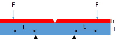
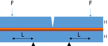
- An elastic substrate, modulus E2, thickness H sits on two points equidistant from the middle of the sample
- A force F is applied from the top, at a distance L from the two points
- A crack in the top is provided in order to define the initial failure point in the adhesion test
- The test device applies a steadily increasing deflection and the required force is monitored to be able to identify the point at which a steady-state crack is produced.
The differences are:
- The single-layer test has a crack through the coating itself, which has a thickness h and a modulus E1
- The multi-layer test has another elastic substrate on top, assumed here to be the same thickness and modulus as the lower substrate, and the pre-crack is created within this top substrate. The thickness of the multi-layer stack is assumed to be "small" with respect to H and plays no part in the analysis.
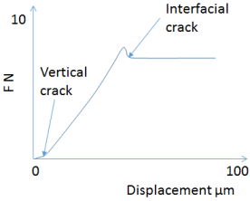 A typical experiment (illustration after Dauskardt) provides a constant displacement rate and monitors the resulting force. At first the force continues the vertical crack so that it reaches the interface. Then there is a steady bending till a blip shows that the crack has moved to the weakest interface. There is then a steady displacement under a constant force, F, used in the calculations.
The reason for the multi-layer test becomes apparent when we look at the formula for the single-layer test. The fracture energy G is given by:
`G=[(F^2L^2)/(E_2b^2h^3)](6η^3-1/(2I))`
The complications arise because we need 3 factors to calculate the final bracketed terms. `Σ=E_1/E_2`, `η=h/H`, `Δ=(1+2Ση+Ση^2)/(2η(1+Ση))`, allowing us to calculate `I=Σ[(Δ-1/η)^2-(Δ-1/η)+1/3]+Δ/η(Δ-1/η)+1/3η^3`. In other words, G contains a complicated mix of the relative thicknesses and moduli of the coating and substrate.
The multi-layer test entirely ignores the properties of the stack sandwiched between the two substrates, allowing G to be calculated easily:
`G=(21F^2L^2)/(16E_2b^2H^3)`
The price for this simplicity is the need to create the sandwich in the first place.
Use the sliders to see how the various parameters interact. Note that input values that might be sensible for the single-layer system might give strange outputs for the multi-layer system and vice-versa; the tests operate in rather different regimes of forces and thicknesses.
4 Point Bend
What do the G values mean? That, too, is complicated. They are "mixed-mode" values because they contain some mix of shear and peel. For the multi-layer test the mix is ~50:50. For the single-layer test the mix depends on the relative thicknesses and moduli in a complicated way not included in the app. This means that the G values don't have an obvious interpretation and, for the single-layer test can't be meaningfully compared between different materials and/or thicknesses because of the mode mixing. Another advantage of the multi-layer test (which is why it has been promoted heavily by Dauskardt and others) is that plastic deformation effects are effectively eliminated. In "simpler" tests the measured G may have almost no relation to intrinsic adhesion because it is dominated by plastic deformations in one or more layers.