Crack Driving Force
Quick Start
This is the last in a series of rather specialised takes on adhesion and is of special interest to those in the semiconductor industry who are often putting different, rather brittle, materials on top of each other. I found it interesting because crack mechanics are so non-intuitive to my sort of brain.
What drives a crack?
The short answer is "thickness and stress". For a given stress, the greater the thickness then the greater the energy tied up by the stress so the more likely failure will be. A common question arises: "For a given stress and a given driving force (strain energy release rate1), what is the maximum thickness of the coating that can be applied without risk of failure?"
As discussed in Appendix D (pp383-9) of Lacombe there is a simple formula relating the critical thickness, hc to G, the driving force (J/m2), E, the modulus (GPa), ν, the Poisson ratio, σ, the stress (MPa) and a numerical factor Z which depends on the geometry:
`h_c=(GE)/(Z(1-ν)σ^2)`
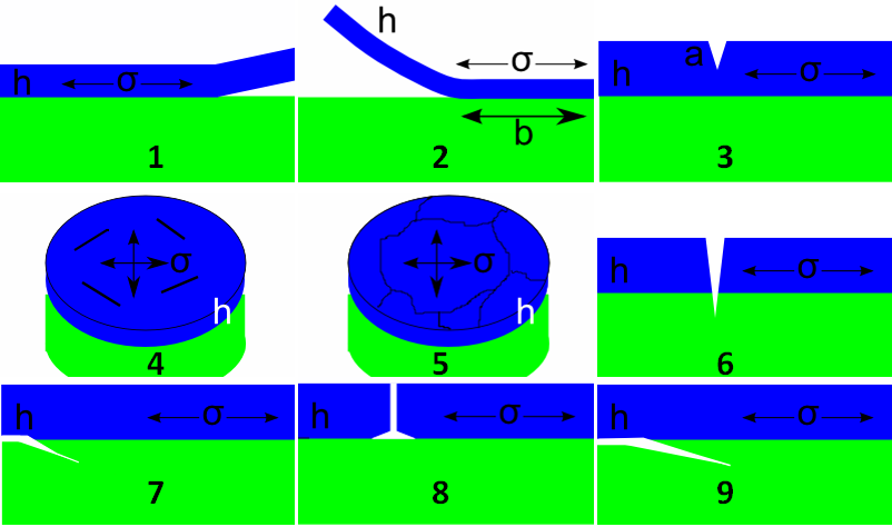
The point of this app is to allow you to choose the geometry (via the slider N from 1 to 9), which provides the value of Z. In some geometries an extra length value a is shown in the diagrams but the calculation depends on the ratio a/h (or a/R) so the value is input as a fraction, f; when not required the value in the f slider is ignored.
Driving Force
Here are a few typical values of E, ν for some standard materials. The values for KI are typical fracture toughness values and Gc is calculated via:
`G_c=(1-ν^2)K_I^2/E`:
| Material | Modulus GPa | ν | KI MPa.m½ | Gc J/m2 |
|---|---|---|---|---|
| Copper | 110 | 0.3 | 10 | 830 |
| Aluminum | 70 | 0.3 | 24 | 7500 |
| Nickel | 210 | 0.3 | 30 | 3900 |
| Steel | 200 | 0.3 | 50 | 11400 |
| Glass | 70 | 0.25 | 0.7 | 7 |
| Glass Ceramic | 110 | 0.25 | 1 | 9 |
| Epoxy | 2.5 | 0.3 | 1 | 360 |
| PI | 2.5 | 0.3 | 1 | 360 |
| PI (low α) | 2.5 | 0.3 | 1 | 360 |
| PET | 4 | 0.3 | 1 | 230 |
| PC | 2.5 | 0.3 | 1 | 360 |
| PMMA | 2 | 0.3 | 1 | 460 |
| PE | 0.8 | 0.3 | 0.5 | 280 |
For a typical example of how these calculations can be used in practice imagine the following scenario. Let's say you are an engineer with a coating company and a line technician runs up and hands you a failed part. You presumably know the elastic properties of the coating and the applied thickness. What you are likely not to know is the residual stress in the coating which can vary significantly due to subtle changes in coating formulation, a miss adjusted curing oven or any of a dozen other slippery processing conditions. If you can identify the failure mode above then you can use the formula to back out a minimum value of the stress in the coating which caused the failure, and from this stress you can perhaps work out what has changed within the process. One can't emphasize enough the importance of controlling the internal stress in a coating in order to ensure its stability in regard to fracture and/or delamination.
1I find the term unhelpful; to me it's a confusing way to talk about work of adhesion. But fracture mechanics people love it. Wikipedia tells us: In fracture mechanics, the energy release rate is the rate at which energy is transformed as a material undergoes fracture. Mathematically, the energy release rate is expressed as the decrease in total potential energy per increase in fracture surface area and is thus expressed in terms of energy per unit area.