Dot Simulation
Quick Start
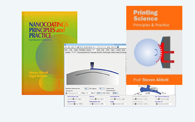
This is a basic simulation of what you might see with inkjet head placement errors.
Credits
This is a simplistic model that I made for my own interest.
Simulation
//One universal basic required here to get things going once loaded
window.onload = function () {
    //restoreDefaultValues(); //Un-comment this if you want to start with defaults
    Main();
};

//Main() is hard wired as THE place to start calculating when inputs change
//It does no calculations itself, it merely sets them up, sends off variables, gets results and, if necessary, plots them.
function Main() {
    //Save settings every time you calculate, so they're always ready on a reload
    saveSettings();

    //Send all the inputs as a structured object
    //If you need to convert to, say, SI units, do it here!
    const inputs = {
        N: sliders.SlideN.value,
        Dot: sliders.SlideDot.value,
        PH: sliders.SlidePH.value,
        Err: sliders.SlideErr.value,
        theta: sliders.Slidetheta.value*Math.PI/180,
        mm: sliders.Slidemm.value,
        rf: sliders.SlideRandom.value,
   };

    //Send inputs off to CalcIt where the names are instantly available
    //Get all the resonses as an object, result
    const result = CalcIt(inputs);
    document.getElementById('Space').value = result.Space;

    //You might have some other stuff to do here, but for most apps that's it for Main!
}

//Here's the app calculation
//The inputs are just the names provided - their order in the curly brackets is unimportant!
//By convention the input values are provided with the correct units within Main
function CalcIt({ N, Dot, PH, Err,theta,mm,rf }) {
    var myrng = new Math.seedrandom('hello.');
      const cost=Math.cos(theta),sint=Math.sin(theta)
    const dpr = window.devicePixelRatio || 1;
    const theCanvas = document.querySelector('canvas')
    const ctx = setupCanvas(theCanvas, dpr);
    const w = theCanvas.width / dpr, h = theCanvas.height / dpr,wN=w/N
    const Space=(mm/N*1000).toFixed(0)+" : "+ (Err*mm/N*1000).toFixed(0) //mm to μm
    Dot*=wN/2 //Divide by 2 because drawDots needs radius
    Err*=wN
    //Set up the rectangle
    ctx.beginPath();
    ctx.fillStyle="white"
    ctx.lineWidth = 5
    ctx.rect(0, 0, w, h);
    ctx.strokeWidth=5
     ctx.fill();
     ctx.stroke()
     //console.log (w,h)
    let count = 0, x=0,y=0, xblip=0, tc=false, xs=0, ys=0,xt=0,yt=0
          for (j = 0-50*Math.abs(sint); j < N * h / w+50*Math.abs(sint); j++) {
              x=0;xblip=0;tc=false
              for (i = 0; i < N; i++) {
                 drawDots(ctx, 'blue', Dot, x+wN*rf*(2*myrng()-1), y+wN*rf*(2*myrng()-1))
                 x+=wN
                 xblip++
                 if (xblip>PH){
                     xblip=0
                     x+=Err
                     tc=!tc
                     xs=x;ys=j*wN
                     xt=i;yt=j
                 }
                 if (tc){
                    x=xs+wN*((i-xt)*cost-(j-yt)*sint)
                    y=ys+wN*((i-xt)*sint+(j-yt)*cost)
                 } else {
                    y=j*w/N
                 }
            count++
        }
    }
    return {
        Space: Space,
    };
}
function drawDots(ctx, col, lw, xv, yv) {
    ctx.fillStyle = col;
    ctx.beginPath();
    ctx.arc(xv, yv, lw, 0, 2 * Math.PI);
    ctx.fill();
}

function setupCanvas(canvas, dpr) {
    // Get the device pixel ratio, falling back to 1.
    var rect = canvas.getBoundingClientRect();
    // Give the canvas pixel dimensions of their CSS
    // size * the device pixel ratio.
    canvas.width = rect.width * dpr;
    canvas.height = rect.height * dpr;
    var ctx = canvas.getContext('2d');
    // Scale all drawing operations by the dpr, so you
    // don't have to worry about the difference.
    ctx.scale(dpr, dpr);
    return ctx;
}
Nozzles in view is the total number of nozzles in view across the screen. This means that the pixel spacing of the nozzles is your screen width/Nozzles. Dot Size is the diameter of the printed dot relative to the nozzle spacing. So a value of 1 means a diameter equal to the nozzle spacing. This becomes clear if you slide to Nozzles=50 so you can clearly see the individual dots.
Now choose a number of Nozzles Per Head. With perfect positioning this doesn't matter. But if there is an Head Placement Error, defined relative to the nozzle spacing of, say, 1 then there will be a nozzle-sized gap between each group of nozzles. The Error can be negative as well as positive. Finally, there might be a rotational error of Head Angle Error θ between each set of nozzles, here we just alternate between perfect 0 angle and an error of θ. Image width scales the values in the output box.
When will errors be visible?
Set up the app on your favourite 4K monitor, work out the size of the pixel dots compared to real world, set up your errors, then view the monitor from a relavant distance. To map onto real printed dots, the actual size of your dots is calculated from your measured Image Width on your own screen, along with the width of the Error line.
Random
The Random slider lets you place the dots at +/- the chosen fraction of nozzle spacing. This obviously helps to hide systematic defects, at the cost of a certain ugliness. How this relates to the statistical variation in an FM (stochastic) screen is an interesting question.