
Mud-Cracking
Quick Start
When we dry a particle- or latex-based formulation, it can sometimes form mud-cracks. It turns out that there is a Critical Crack Thickness below which you get no cracking. Here we calculated CCT using a mix of known and tricky input values.
Credits
Inspiration and key literature for tackling this problem were kindly provided by Dr Bernhard Kainz from Dow Coating Materials.
Mud-Cracking
Warning:  include(apps/js/mud-cracking.v1.js): Failed to open stream: No such file or directory in /var/www/vhosts/stevenabbott.co.uk/httpdocs/practical-coatings/Mud-Cracking.php on line 33


Warning:  include(): Failed opening 'apps/js/mud-cracking.v1.js' for inclusion (include_path='.:/opt/plesk/php/8.3/share/pear') in /var/www/vhosts/stevenabbott.co.uk/httpdocs/practical-coatings/Mud-Cracking.php on line 33
 The CCT equation
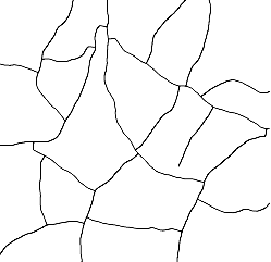
As a coating with a large fraction of particles dries it can spontaneoulsy form cracks looking like those in the image. The reasons for this typical mud-cracking pattern are given in the Cracks app.
The driving force for the cracking is a maximum capillary pressure P calculated from the particle radius R, the surface tension γ, the contact angle θ and the close packed fraction φ.
`P=(2γ)/r(3φcosθ)/(2(1-φ))`
The resistance to cracking depends on a "coordination number" M, which is related to φ and the "shear modulus" of the particles G. The stresses increase with thickness so there is a Critical Cracking Thickness, CCT, above which mud-cracks appear. One form of the equation to calculate the CCT is from Tirumkudulu:
`"CCT"=0.64((GMφR^3)/(2γ))^½((2γ)/(PR))^½`
It looks as though the factors of `γ^½` cancel out, but the CCT does depend on γ via the equation for P. Having P in the equation (rather than a more complicated equation using the other factors) is a reminder that a larger P means a smaller CCT, so one way to make formulations more crack resistant is via γ, θ and φ.
The parameters
R, γ and θ are relatively straightforward. φ depends on your system. Conventionally, φ=0.64 but if your particles flocculate, φ might be as low as 0.53. This affects M which is ~6.5 for the tight packing and ~5 for the flocculated packing, i.e. the number of particles around any other particle decreases as the packing gets less tight.
That leaves us with G. In other papers, G is more like an "energy release rate", i.e. a measure of dissipative adhesion. So instead of G they have GcE* where Gc is a classic dissipative adhesion parameter that some like to call energy release rate, and E* is the tensile modulus, adjusted for Poisson ratio. This doesn't really help. Many experiments are carried out on perfect spherical particles of zero interest to practical coaters. Once you have polymers, latices, minimum film-forming temperatures and so forth, G becomes more complex or Gc becomes more related to polymeric energy dissipation, which is nice to know but still not so helpful. Some papers even point out that when you make ceramics, the green strength (before firing) depends on the mechanical properties of the polymer holding particles together (of course) but also on whether the polymer is concentrated at the joins or is smeared around the particles. See the Ceramic Green Strength app. But it's still difficult to apply these ideas.
So what's the point? The answer is that the theory, which is well-tested, helps you pick apart key influences and allows you to think through what might be usable for your own system.
The real world
There is an especially good guide to real-world systems provided by Dr Martin Murray at AkzoNobel: Cracking in coatings from colloidal dispersions: An industrial perspective. which uses the same Tirumkudulu equation as a starting point. More recent academic work confirms the general ideas and some of the points are as follows. However, the most important point has a section to itself:
- Shape, over a range of typical particles, makes relatively small difference
- Soft particles have no CCT - they simply fuse
- A mix of soft and hard particles can start to crack ~ 50% hard particles when they can percolate across the film.
- Lowering the (dynamic) surface tension isn't a straightforward win. That will also decrease the contact angle, which increases P.
- Experiments often show small effects of drying rates - but these are often super-slow idealised experiments or for slow-drying paints. For coatings that dry in seconds it's highly likely that "happy" formulations that keep moving particles for as long as possilbe, will crack less than "unhappy" ones. Putting it another way ...
- ... the longer the available "relaxation time", the more viscous flow that can reduce stress.
- A bi- or multi-modal particle distribution where small particles fill gaps between larger particles obviously help increase CCT.
- You can measure stress build-up in a coating using the cantilever approach described in the Stress from Bending app. The laser-based approach is the "official" method, but casting onto flat sheets of, say, PET film provides a quick and informative method for those without the laser setup.
- Extra polymers can sometimes hinder (if they make G too small) but mostly help as they can link up otherwise weakly-connected particles. As mentioned above, there's a subtle issue here described in the Ceramic Green Strength app. If the polymer congregates at the intersections of the particle it has a bigger effect on strength than if "wasted" by coating most of the particle.
Specific Surface Area
Dr Murray generously provided me with some extra insights into the 2-year project behind that report. Although the basic equation shows a correlation with R, real-world systems correlate better with SSA, Specific Surface Area. As an example, Dr Murray explained that you can have a range of Aerosils all of the same 100-200nm size but with the CCT being much larger for 50m²/g particles than for 1500m²/g. The effective capillary size between particles with high rugosity is much smaller, so the crack energies are much higher. Although TiO2 particles are made small (~300nm) by design (optimum hiding power), they are relatively solid/smooth so are not as crack-prone as we might expect. The conversion from SSA to an effective capillary radius R is provided by the paper by Lee White quoted in the presentation, J.Colloid and Interface Sci. 90, 1982, 535-538. Where φp is the packing fraction (assumed to be your chosen close-packed fraction) and ρp is the density of the particle itself:
`R_(eff)=(2(1-φ_p))/(φ_pρ_pSSA)`
The calculated values seem rather too small to be realistic, but it gives you an idea of the scale of the effect.